| Model Name | NF931 |
| Part Number | JNF931G32-4125
JNF931G32-4105
JNF931G64-4125
JNF931G64-4105 |
| Form Factor | 3.5" SBC (148 x 102mm) |
| Processor | Intel® Celeron J4125 Processor Quad Core 2.00 GHz - 2.70 GHz, 10W TDP
Intel® Celeron J4105 Processor Quad Core 1.50 GHz - 2.50 GHz, 10W TDP
* Ships with flat silver heatsink for direct attaching to a surface |
| Memory | 2 * 260-pin DDR4-2400 up to 8GB Total |
| Graphics | Intel HD Graphics 600, 250MHz - 750MHz |
| Audio | Realtek ALC662VD HD Audio |
| LAN | 1 x Intel i211AT Gigabit LAN |
| Storage | 1 x 32/64GB eMMC
1 x M.2 SATA & PCIE 3.0 x2 NVME 2242/2280
1 x SATA3 6Gb/s Connector |
| Super IO | FINTEK F81804U |
| TPM | OEM Option: Onboard TPM v1.2 or v2.0 |
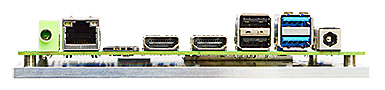
| Back Panel Connectors |
1 3.5mm Audio Jack (Line-out)
1 RJ-45 ports (10/100/1000)
1 Micro SIM Card Slot
2 HDMI 2.0 (4096 x 2160 @ 60Hz)
2 USB 2.0 ports
2 USB 3.1 Gen1 ports
1 12V DC-in jack
|
| Onboard I/O Connectors |
1 M.2 SATA & PCIE 3.0 x2 NVME 2242/2280
1 M.2 PCI-E 2230 E Key for WiFi
1 Full Size Mini PCI-E Slot
1 SATA3 6Gb/s Connector
1 USB Pin Header for up to 2 additional USB 2.0 Ports
1 Serial Port Headers (RS232)
1 40-pin eDP (4096 x 2304 @ 60Hz)
1 AT/ATX Mode Jumper
1 8-bit GPIO Header
1 4-pin 3W Amplifier Header
1 9-pin HD Audio Header
1 9-pin Front Panel Header
1 4-pin Fan Headrer
1 4-pin Power-out Connector for 2.5" HDD/SSD
1 2-pin +12V Alternate Power-In (Mating plug: JST VHR-2N or TE 1-1123722-2)
|
| Power Supply for NF931 |
External Power Supply – the board can be powered with a +12V external power supply though a DC connector on the back panel. The rear +12V DC jack accepts plugs with an inner diameter (ID) of 2.5 mm and an outer diameter (OD) of 5.5 mm, where the inner contact is +12V (±5%) and the shell is GND.
Internal Power Supply – the board can alternatively be powered via the internal +12V 2-pin power connector, where pin 1 is +12V and pin 2 is GND. The internal 2-pin power connector accepts a JST VHR-2N or TE 1-1123722-2 plug from the power supply.
Caution: There is no isolation circuitry between the external +12V DC jack and the internal 2-pin power connector. It is the system integrator's responsibility to ensure no more than one power supply unit is or can be attached to the board at any time and to ensure the external +12V DC jack is covered if the internal 2-pin power connector is to be used.
|
| Market Segments Supported |
√ Digital Security & Surveillance
√ Digital Signage
√ Gaming
√ Industrial Automation/Control
√ Medical
√ Retail (POS/Kiosk/ATM)
√ Networking/Storage Server/Mail Server/Print Server
√ Thin Client
√ HTPC
|
| Environment |
Operating Temperature : 0 ~ 40°C
Storage Temperature : -20 ~ 85°C
|