| Model Series | JF35-ADN1 |
| Part Number | JF35-ADN1-N97000 | JF35-ADN1-N97008 (64GB eMMC and TPM 2.0) |
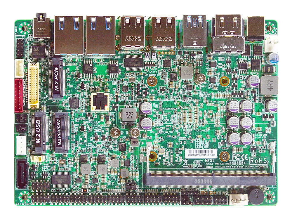
| Form Factor | 3.5" SBC (148 x 102mm) |
| Processor | Intel® Processor N97, up to 3.60 GHz, 4-Core 4-Thread, 12W TDP (Products formerly Alder Lake-N)
* Ships with flat silver aluminum heatsink for direct attach |
| Memory | 1 x 262-pin Single Channel DDR5-4800 SO-DIMM up to 32GB Total |
| Graphics | Intel® UHD Graphics
Up to 3 Displays |
| Audio | Realtek ALC897/ALC888S HD Audio, 3W Amplifier |
| LAN | 2 x Intel I226-V PCIe 2.5GbE |
| Storage | 1 x SATA3 6Gb/s
1 x M.2 (PCIe 3.0 x2, M-key, 2280 NVMe) | 1 x SATA3 6Gb/s
1 x M.2 (PCIe 3.0 x2, M-key, 2280 NVMe)
Onboard 64GB eMMC |
| Super IO | FINTEK F81966D |
| TPM | Intel fTPM 2.0 (PTT) | Intel fTPM 2.0 (PTT)
Onboard NUVOTON TPM v2.0 |
| Back Panel Connectors |
1 +12V - 28V 2.5mm Diameter DC Power Jack
2 HDMI 2.0b (4096 * 2160 @ 60Hz)
1 USB 3.2 Gen 2 (10 Gb/s)
1 USB 3.2 Gen 2 (10 Gb/s) Type-C with DP 1.4 (4096 x 2304 @ 60Hz)
4 USB 2.0 Port
2 RJ45 LAN (10/100/1000/2500)
1 3.5mm Combo Line-out/MIC Jack

|
| Onboard I/O Connectors |
1 SATA3 6Gb/s Connector
1 M.2 M-Key, 2280 (PCIe 3.0 x2 NVMe)
1 M.2 B-key, 3042/3052 (USB3.2/USB2.0 for 3G/LTE Modem)
1 M.2 E-key, 2230 (PCIe 3.0 x1/USB 2.0/CNVi for WiFi)
6 Serial Headers (5 * RS232, 1 * RS232/422/485, PH 2.0)
2 USB Pin Headers for 4 additional USB 2.0 Ports
1 LVDS/eDP (1920 * 1200 @ 60Hz, BIOS Selectable)
1 Inverter
1 Nano SIM Socket (Bottom)
1 8 bit GPIO Header
1 4-pin SMBUS Header
1 4-pin Fan Header
1 9-pin Front Audio Header
1 Speaker Header
1 Chassis Intrusion Header
1 AT/ATX Mode Jumper
1 4-pin SATA Power Output (Male)
1 2-pin +12V – 28V Alternate Power-In (Mating plug: JST VHR-2N or TE 1-1123722-2)
|
| Power Supply for JF35-ADN1 |
External Power Supply – the board can be powered with a +12V – 28V external power supply though a DC connector on the back panel. The rear +12V – 28V DC jack accepts plugs with an inner diameter (ID) of 2.5 mm and an outer diameter (OD) of 5.5 mm, where the inner contact is +12V – 28V and the shell is GND.
Internal Power Supply – the board can alternatively be powered via the internal +12V – 28V 2-pin power connector, where pin 1 is +12V – 28V and pin 2 is GND. The internal 2-pin power connector accepts a JST VHR-2N or TE 1-1123722-2 connector from the power supply.
Caution: There is no isolation circuitry between the external +12V – 28V DC jack and the internal 2-pin power connector. It is the system integrator's responsibility to ensure no more than one power supply unit is or can be attached to the board at any time and to ensure the external +12V – 28V DC jack is covered if the internal 2-pin power connector is to be used.
|
| Market Segments Supported |
√ Industrial PC
√ Factory Automation
√ Retail (POS/Kiosk/ATM/Digital Signage)
√ Digital Security / Surveillance
√ Panel PC
|
| Environment |
Operating Temperature : -20 ~ 60°C
Storage Temperature : -20 ~ 85°C
Humidity: 10% ~ 90% RH @40°C (non-condensing)
|